El cable de compensación de termopar se ha utilizado ampliamente en la medición de la temperatura del termopar. Entendiendo el principio, la función, el método de acción y las precauciones del cable de compensación de termopar, podemos dar un juego completo sobre el papel del cable de compensación de termopar, de lo contrario será contraproducente. En la producción industrial, aunque el termopar se ha utilizado ampliamente en la medición y el control de la temperatura como sensores de temperatura, las personas están familiarizadas con esto, pero si no presta atención al método de uso correcto, causará grandes desviaciones en la medición de la temperatura y el control de la temperatura. Incluso causando directamente las pérdidas económicas, debe tomarse en serio.
1. Principio
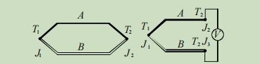
Un circuito compuesto por dos conductores metálicos diferentes A y B conectados juntos se llama termopar. Si la temperatura de unión T1 y T2 son diferentes, se generará un potencial eléctrico en el circuito, generalmente llamado potencial termoeléctrico. Cuando los materiales de A y B son constantes, el potencial termoeléctrico depende de la diferencia de temperatura entre T1 y T2. Cuando los materiales de A y B son constantes, el potencial termoeléctrico depende de la diferencia de temperatura entre T1 y T2.
De acuerdo con la ley de los conductores intermedios de termopar, siempre que la temperatura de las uniones J2 y J3 en la figura derecha sean las mismas, ambos son T2, y ambos cables de conexión son el mismo material homogéneo, y las figuras derecha e izquierda son equivalentes .
2. Cable de compensación
Después de instalar el termopar se instala en el campo, debe conectarse al instrumento para medir o controlar la temperatura. Dado que el termopar siempre se usa a cierta distancia del instrumento de medición o control, la temperatura en el terminal de termopar no es la misma que la temperatura en la entrada del instrumento. En términos generales, se necesita un problema de compensación de temperatura de la unión de referencia, y el cable de compensación no compensa la unión de referencia, solo extiende la unión de referencia a una posición específica para el procesamiento, por lo que el cable de compensación también se llama cable de extensión de termopar. Hay dos tipos de materiales para hacer cables de compensación. Una es que dentro de un rango de temperatura específico, el potencial termoeléctrico generado por el cable de compensación es similar al del termopar a utilizar, que se llama cable de compensación; El otro está hecho de material de termopar, conocido como cables de extensión. Tales cables extendidos obviamente no son posibles para el termopar de metal noble. El cable de compensación es una parte importante de la medición del termopar, por lo que el modelo correspondiente debe seleccionarse de manera correcta y razonable, y los cables de compensación de diferentes tipos no se pueden mezclar.
3. Errores comunes en uso
(1) Los polos positivos y negativos del cable de compensación de termopar y el termopar se invierten
Si los polos positivos y negativos del cable de compensación termopar y los polos positivos y negativos del termopar están conectados reversamente, y los polos positivos y negativos del termopar están conectados con los polos positivos y negativos del instrumento correctamente, no solo lo hace. no jugar un papel de compensación, pero el error es mayor que el de no conectar el cable de compensación. También se duplicará, por lo que la polaridad debe prestarse atención cuando el cable de compensación está conectado.
Si no se puede determinar la polaridad del cable de compensación termopar, podemos tomar un trozo de cable de compensación, retirar el aislamiento en un extremo, retorcerlos, ponerlos en una taza de agua caliente y medir los dos cables en el otro extremo con El rango de voltaje de CC más bajo de un multímetro ordinario. Se mostrará lo positivo y negativo del voltaje medido, y el polo positivo de la señal es el polo positivo del cable de compensación.
<33
(2) Tipo incorrecto de conductor de compensación utilizado
El mismo tipo de cable de compensación coincide con el mismo tipo de termopar. Si el tipo de cable de compensación seleccionado es incorrecto, también se producirán errores.
(3) Cable de compensación mezclado con alambre común
En aplicaciones prácticas, a menudo se encuentra que el cable de compensación no es lo suficientemente largo como para conectarse con un cable ordinario, o una sección de cable ordinario se conecta después de que se rompe el cable de compensación. Por lo general, el potencial diferencial del termopar metálico base es mayor que el del termopar de metal noble, y la influencia del termopar de metal noble es mayor.
4. Precauciones
(1) Opciones
El cable de compensación debe seleccionarse correctamente de acuerdo con el tipo de termopar y la ocasión. Por ejemplo, el tipo K de K debe elegir el cable de compensación del tipo K y seleccionar el rango de temperatura de trabajo de acuerdo con la ocasión de la aplicación. Por lo general, la temperatura de trabajo de KX es de -20 ~ 100, y el amplio rango es -25 ~ 200 â. El error del nivel normal es ± 2.5, y el error del nivel de precisión es ± 1.5.
(2) conectar
Lo más cerca posible de las dos uniones de los terminales de termopar, intente mantener las dos uniones a la misma temperatura. La temperatura de la conexión con el terminal del instrumento debe ser lo más consistente posible. Donde hay un ventilador en el gabinete de instrumentos, las juntas deben protegerse para que el ventilador no sople directamente a las juntas.
(3) Usar longitud
Debido a que la señal del termopar es muy baja, que está en el nivel de î¼ V, si la distancia utilizada es demasiado larga, la atenuación de la señal y el acoplamiento de interferencia de electricidad fuerte en el medio ambiente pueden distorsionar la señal del termoplio, lo que resulta En la medición inexacta y el control de la temperatura, se producirán graves fluctuaciones de temperatura.
Por lo general, es mejor controlar la longitud del cable de compensación de termopar dentro de los 15 m. Si excede, se recomienda usar un transmisor de temperatura para transmitir la señal. El transmisor de temperatura convierte el valor potencial correspondiente a la temperatura en una transmisión de corriente de CC y tiene una fuerte anti-interferencia.
(4) Configuración
Los cables de compensación deben ser alteados de las líneas eléctricas y las fuentes de interferencia. Donde es inevitable cruzar, trate de usar el cruce tanto como sea posible en lugar de paralelo.
(5) Cable de compensación protegido
Para mejorar el rendimiento anti-interferencia de los cables de conexión de termopar, se pueden usar cables de compensación blindados. El efecto es mejor para las ocasiones en las que hay muchas fuentes de interferencia en el sitio. Sin embargo, la capa de blindaje debe estar estrictamente conectada a tierra, de lo contrario la capa de blindaje no desempeñará el papel de blindaje, sino que mejorará la interferencia.


 Network IPv6 compatible con