La aplicación precisa y estandarizada de sensores es la clave para garantizar el funcionamiento normal de los equipos de medición y control y realizar tecnología de proceso en la producción industrial. Fallas de operación del equipo y accidentes de producción causados por una configuración incorrecta y el uso de sensores de medición de temperatura e instrumentos de control de medición en el sitio de operación de horno de calefacción industrial. Estas fallas y accidentes hacen que el control de temperatura del termómetro sea inexacto, lo que afectará el proceso de producción de procesamiento térmico y eficiencia laboral, lo que resulta en una reducción en la calidad del producto. En casos severos, el lote del producto no estará calificado e incluso causará daños al equipo de horno eléctrico, lo que resulta en el cierre del horno eléctrico y el accidente de daño. Por lo tanto, en el sitio de producción de calefacción industrial, es necesario asegurarse de que el uso y el soporte de sensores de temperatura, dispositivos e instrumentos se estandaricen. El termocoza es un dispositivo de sensor para la pantalla de temperatura y el sistema de control de un horno eléctrico para calefacción industrial.
1. Uso de desajuste de alambre de compensación y termopar
La indicación de temperatura por encima de 1000â en la zona de alta temperatura en el taller de procesamiento térmico es demasiado alta. Cuando la temperatura es de 800 y inferior, el valor de la visualización de temperatura también es demasiado grande.
1.1. Método de tratamiento y análisis de causa
(1) Método
La selección incorrecta de la coincidencia de cable de compensación conduce a una medición de temperatura inexacta. Reemplace el cable de compensación correspondiente y se elimina la falla.
(2) Causa
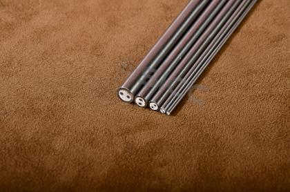
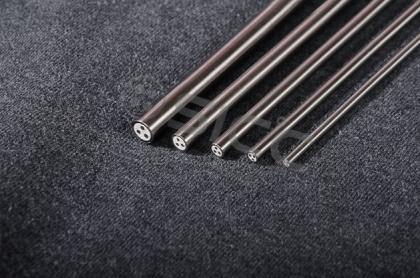
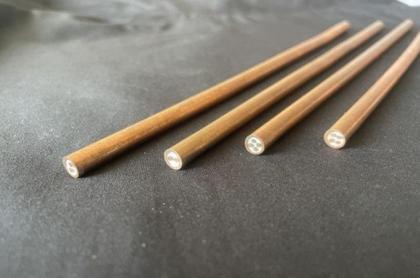
Cuando el instrumento se instaló en el sitio, se ignoró la relación coincidente entre el cable de compensación y el termopar, lo que resultó en una falla. El principio de medición de temperatura del termopar se basa en la temperatura constante de la unión fría. Por lo tanto, el electrodo negativo del termopar debe establecerse en un área con temperatura constante en el sitio de instalación y luego lograr el propósito de medición precisa a través de una cierta compensación de temperatura; Este tipo de compensación de temperatura es la compensación de la unión fría. Cabe señalar que la función del cable de compensación no es compensar el potencial de la unión fría: para mantener la temperatura de la unión fría de la temperatura del termopar que mide constante el electrodo, el electrodo debe extenderse, pero los electrodos de Los termopar son todos metales preciosos. Por lo tanto, la práctica habitual es extender el extremo frío del electrodo termoeléctrico con un alambre metálico con propiedades termoeléctricas similares al material del electrodo termoeléctrico a temperatura ambiente (0 ~ 1009). Al área lejos de la fuente de calor y la temperatura es estable, el cable de este material se llama cable de extensión o alambre de compensación. Obviamente, la función del cable de compensación es "compensar la falta de longitud del termodo". Según la idea de que las características termoeléctricas del cable de compensación y el termodo son similares a temperatura ambiente, el cable de compensación y el termopar se usan juntos.
2. Uso indebido de polos positivos y negativos de cable de compensación y termopar
2.1. No hay indicación de temperatura después de reinstalar en su lugar
2.2. Método de tratamiento y análisis de causa
(1) Método
<33
Si el instrumento y el termopar se ejecutan normalmente, la verificación está calificada. Tales problemas se consideran principalmente desde la perspectiva de la instalación. El puntero del medidor se desvía en la dirección opuesta, lo que indica que no hay problema con la conexión de línea. Use un medidor milivoltio para medir el termopar y el terminal de entrada del instrumento. Si se encuentra que los polos positivos y negativos del termopar se invierten, ajuste los polos positivos y negativos. El instrumento indica normal, pero encuentra que el valor de temperatura indicado es menor que el valor de temperatura real, excluyendo la compensación de la unión fría y la calibración del punto cero. Observe si los polos positivos y negativos del cable de compensación de termopar se invierten, se ajustan al correcto y el equipo vuelve a la normalidad.
(2) Causa
La razón por la cual el termopar y la compensación de cables pueden convertir las señales de temperatura en señales potenciales es que diferentes metales producen diferentes potenciales bajo la misma diferencia de temperatura. Esto permite que los diferentes electrodos del termopar y su cable de compensación tengan polaridad positiva y negativa con respecto a la salida. La polaridad inversa naturalmente hace que el medidor no pueda mostrar.
3. Compensación insuficiente de unión fría
3.1. Una gran cantidad de controladores de temperatura ahora indican fallas bajas.
3.2. Método de tratamiento y análisis de causa
(1) Método
Se midió realmente el valor milivoltio en el extremo de entrada del termostato, y se calculó la temperatura teórica. En comparación con la temperatura real del horno eléctrico, se descubrió que el transmisor de temperatura tenía un problema de ajuste de punto cero bajo. Calibre el punto cero del termostato, y se elimina la falla.
(2) Causa
Este es un problema de compensación de unión fría. El valor teórico de la temperatura de la unión fría de un termopar es 0. Pero en el campo industrial, la unión fría del termopar generalmente está a temperatura ambiente. El potencial recibido por la entrada del transmisor de temperatura es igual al potencial E1 generado por el termopar menos el potencial de unión fría (potencial de temperatura ambiente) E2, (V = E1-E2).
En la sala de calibración del instrumento con baja temperatura ambiente, y el potencial termoeléctrico generado por el extremo frío es E2D; En el sitio de instalación del equipo, la temperatura ambiente es más alta que la sala de calibración, y el potencial termoeléctrico del extremo frío en este momento es E2H. Esto hace que el potencial de entrada del instrumento v sea más bajo que el del sitio de calibración del instrumento en el sitio de producción. Después de usar el cable de compensación para hacer que la temperatura de la unión fría del termopar alcance una temperatura relativamente estable, la compensación de temperatura de la unión fría debe llevarse a cabo de acuerdo con la temperatura de funcionamiento real de la unión fría. El método común y conveniente es ajustar el punto cero del instrumento para lograr el propósito de la compensación. El cable de compensación solo sirve para extender la unión fría, y no puede compensar el error de medición de temperatura causado por la temperatura de la unión fría no es 0 (porque el valor de división del termopar se establece en la unión fría 0â).
4. Falla de instalación de compensar el cable
4.1. El puntero del indicador de temperatura se eleva hacia arriba y hacia abajo, y el puntero apunta al máximo cuando es estable.
(1) Verifique la fuente de alimentación, el cuerpo del horno eléctrico, el instrumento de control y el cuerpo de termopar son normales, observan el cable de compensación y encuentre que el cable de compensación y el cable indicador solo están conectados al cable directamente sobre el tornillo de cableado. Después de la operación, el calor y la ablación causan contacto con contacto. Vuelva a procesar la junta, el cable de compensación original es el cobre-cobre-níquel, engarce la orquinabro de alambre de acero (terminal) en ambos extremos y aplica pasta de vaselina neutra en la conexión para evitar la corrosión. El equipo volvió a la normalidad y ha estado funcionando sin falla durante mucho tiempo.
(2) La resistencia de contacto entre el cable de compensación y el terminal de entrada del instrumento aumenta, lo que hace que aumente el potencial del terminal de entrada del instrumento.
4.2. El puntero del indicador de temperatura se eleva hacia arriba y hacia abajo, a veces indica que la temperatura es normal, y a veces no hay pantalla de temperatura.
(1) Método: El electrodo positivo del cable de compensación está dañado y conectado a tierra en el punto de contacto con la cubierta del equipo.
(2) Causa: cuando el cable compensador está conectado a tierra, no hay salida de señal al instrumento indicador; Cuando el suelo se desconecta temporalmente del suelo debido a alguna razón (tirando o en movimiento), el dispositivo es normal; Cuando se produce una conexión a tierra intermitente, el puntero de pantalla fluctúa hacia arriba y hacia abajo.
4.3. El puntero del instrumento indicador fluctúa hacia arriba y hacia abajo inestables, pero el rango de fluctuación no es grande. La fluctuación es obvia durante el proceso de calefacción; El horno eléctrico es estable o ocasionalmente fluctúa durante la preservación del calor.
(1) Método: La fluctuación del puntero del instrumento de visualización de temperatura está relacionada con el cambio de la corriente de calentamiento. El cable de compensación se coloca en la misma dirección que el cable principal de la fuente de alimentación de calefacción del horno de resistencia y se agrupa. Coloque el cable de compensación y el cable de conexión del instrumento por separado para aislar el cable de compensación de la línea de alimentación principal, y se elimina la falla.
(2) Causa: el cable compensador está sujeto a interferencia electromagnética de la red eléctrica.


 Network IPv6 compatible con