Con el rápido desarrollo de la ciencia y la tecnología, el rango de aplicaciones a la temperatura sensores se está volviendo más y más amplio, y se pueden ver en todas partes en la vida diaria, lo que brinda una gran comodidad a la vida y la producción industrial de las personas. Los sensores de temperatura combinan orgánicamente las propiedades de material y circuito relacionados con semiconductores para lograr el propósito de medir con precisión la temperatura ambiente. Puede medir eficientemente la temperatura de varios objetos y evitar el fenómeno del cortocircuito de los cables debido al sobrecalentamiento de los electrodomésticos.
1. Sensor
1.1. Definición y propósito
Un sensor de temperatura se define como un sensor que detecta la temperatura de un objeto o entorno y lo convierte en información de salida utilizable. Por lo general, los sensores de temperatura están hechos para combinar el valor de resistencia del NTC con el cambio en las señales de temperatura y salida, convirtiendo de manera efectiva y exitosa cantidades físicas en cantidades eléctricas, para medir con precisión la temperatura como un dispositivo. Los sensores de temperatura pueden medir y controlar la temperatura de ciertos objetos, pero también para determinar la velocidad del viento, la velocidad de flujo, la medición de la temperatura, la potencia de microondas y el ultravioleta, la luz infrarroja, no solo que los sensores de temperatura también se usan al mismo tiempo en refrigeradores , Televisores, calentadores de agua, aires acondicionados, monitores de computadora, equipos en la cocina, automóviles y muchas otras áreas. Hoy en día, los sensores de temperatura se utilizan en una amplia gama de productos para evitar cortocircuitos en el cableado eléctrico. Esta es la razón por la cual los sensores de temperatura son tan importantes para nosotros.
1.2. Clasificación
En la actualidad, los sensores de temperatura de uso común son sensores de temperatura de resistencia al platino, sensores de temperatura de la unión PN, sensores de temperatura integrados, etc. Según las necesidades del sensor y el entorno para elegir diferentes sensores de temperatura.
Los sensores de temperatura de resistencia al platino son sensores comunes cuya función deriva de la naturaleza de la resistencia al platino. Un conductor de metal fluctuará en resistencia como resultado de los cambios de temperatura. El principio del sensor de temperatura de resistencia al platino es detectar la temperatura ambiente detectando el cambio de resistencia al platino.
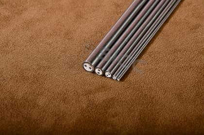
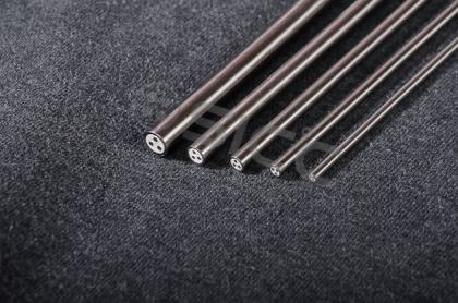
Si se usa un conductor de metal para preparar el sensor de temperatura, se requiere tener alta resistividad, baja capacidad de calor y velocidad de reacción rápida. Este tipo de metal, como hierro, níquel, platino, cobre, etc. Sin embargo, debido a la pobre estabilidad del hierro y el níquel, es difícil purificar, el cobre y el platino tienen un mejor rendimiento. Las propiedades del platino son más adecuadas para el medio ambiente que enfrentan los sensores de temperatura. Por lo tanto, las resistencias de platino son muy comunes para la preparación de sensores de temperatura.
En 0 ° C ~ 630.74 ° C La relación de mapeo es RT = R0 (1 + AT + BT2), en -200 ° C ~ 0 ° C La relación de mapeo es RT = R0 (1+ AT + BT2 + CT3).
El principio del sensor de temperatura de la unión PN se deriva del hecho de que el voltaje de unión de la unión PN del transistor puede mostrar un cambio aproximadamente lineal característico con la temperatura ambiente medida, por lo que el sensor de temperatura preparado utilizando el transistor puede completar la temperatura de la temperatura. medición. En un modo de corriente determinado, existe una buena relación lineal entre el voltaje directo de la unión PN y la temperatura ambiente.
El sensor ISA del sensor de temperatura integrado que integra circuitos auxiliares y transistores sensibles a la temperatura. Este sensor de temperatura es similar a un circuito integrado, con un rendimiento relativamente estable y una relación lineal ideal.
2. Objetivos de diseño
<33
2.1. estructura de diseño
El sensor de temperatura es un elemento de detección de temperatura, y la salida de su señal se completa procesando los datos por la microcomputadora de un solo chip, y el valor de temperatura se muestra a través del tubo digital. La temperatura proporcionada debe mostrarse a través de una fuente de alimentación externa de 5 ~ 12 v CC, el rango se controla dentro de -55 ° C ~ 125 ° C, la precisión debe alcanzar 1 ° C y el tubo digital puede mostrar la temperatura entera. El sensor de temperatura tiene función de alarma de sonido y luz. Si la temperatura de alarma se establece en 30 ° C, estará en un estado de trabajo normal cuando la temperatura esté dentro de los 30 ° C; Por el contrario, una vez que la temperatura alcanza los 30 ° C, el diodo emitirá una luz y le dará un sonido, es el sonido de alarma del timbre. Si no hay necesidad de controlar la temperatura durante el trabajo, se puede configurar con anticipación para aumentar la temperatura de la alarma adecuadamente. Si necesita controlar una pequeña parte de la temperatura durante el trabajo, puede usar el cable de plomo para dirigir el sensor de temperatura.
Se puede ver en el concepto de diseño que el sistema de medición de temperatura tendrá cuatro módulos: sistema de adquisición, sistema de procesamiento de visualización, sistema de alarma y sensor de temperatura. La señal de temperatura medida se envía al microprocesador a través de la línea de transmisión, se convierte en una señal digital y se envía a la calculadora para un análisis y procesamiento integrales.
2.2. Requisitos de producción
<32
Durante el proceso de producción, hay 3 problemas que necesitan atención.
<33
<34
(1) Preste atención a si el símbolo de "° C" se invertía. Durante el proceso de soldadura, preste especial atención al tubo digital del símbolo de Celsius para colocarse al revés para evitar el fenómeno de la dirección inversa;
<35
<36
(2) Es mejor instalarlo en el tablero, de modo que no solo se guarde el espacio, sino que también el efecto de disipación de calor es muy bueno. En condiciones de temperatura normal, la temperatura del bloque estabilizador de voltaje generalmente permanecerá normal;
<37
<38(3) Los condensadores, triodos y diodos emisores de luz no deben revertirse. Si la conexión se invierte, su función no se puede mostrar. Al mismo tiempo, la soldadura no debe ser demasiado durante el proceso de soldadura para evitar la ocurrencia de cortocircuitos.
<39
<40
2.3. Instalación y puesta en marcha
<41
<42
Antes de depurar, asegúrese de verificar nuevamente el circuito para asegurarse de que la soldadura sea precisa y si hay un cortocircuito en cada pin. Al mismo tiempo, al depurar, asegúrese de que la placa de circuito esté trabajando a temperatura ambiente para garantizar que todo el trabajo sea preciso antes de conectar la fuente de alimentación.
<43
<44
3. Principio de trabajo de circuito e introducción
<45
<46
3.1. Workingprinciple
<47
<48R1 es un componente de resistencia sensible a la temperatura. Cuando cambia la temperatura, se cambiará el valor de resistencia de R1. En principio, la fuente de corriente constante construida por el regulador de voltaje de tres terminales LM317 generará una señal de voltaje que cambia con la temperatura para la excitación R1, y luego a través de la precisión del amplificador del instrumento INA114 amplifica la señal de voltaje de detección al valor de voltaje estándar UO . El equipo de adquisición de back-end convierte a UO en señales digitales, y las señales digitales se registrarán en la base de datos en forma de datos y se convertirán en varias pantallas.
<49
<50
<51
<52
<53
En la actualidad, desde la perspectiva de la aplicación, los sensores de temperatura convencional se dividen en sensores de temperatura de contacto y sin contacto, y pueden dividirse en resistencia térmica y termopar de acuerdo con la división del material.
<54
<55
3.2. ContactTemperaturesensor
<56
<57El extremo de detección del sensor de temperatura de contacto debe estar en contacto directo con el objeto a detectar. También se llama termómetro. El termómetro sigue el balance de calor formado por convección y conducción. Con una fuerte precisión y puntualidad, puede medir rápidamente la temperatura del objeto medido, especialmente en la medición de temperatura local, mostrando la distribución de la temperatura. Sin embargo, para los objetos con baja capacidad térmica, los errores de detección son propensos a ocurrir. En términos de materiales y principios utilizados de manera integral, los termómetros se pueden dividir en tipo líquido, tipo de presión y tipo de metal, que se utilizan ampliamente en campos comerciales, industriales y agrícolas. En la vida diaria de las personas, el termómetro también solía medir su propia temperatura.
<58
<59
3.3. No contactemperaturateSensor
<60
<61El sensor de temperatura sin contacto es completamente opuesto al sensor de temperatura de contacto, no tiene contacto directo con el objeto detectado. Su ventaja es que se puede usar para medir objetos con una pequeña capacidad de calor y objetos en movimiento, e incluso los objetos cuyos cambios de temperatura muy rápido pueden mostrar rápidamente la temperatura de su superficie. Dado que el elemento de medición de temperatura del sensor de temperatura sin contacto no toca el objeto a medir, también se puede utilizar para la medición de la temperatura de la infraestructura pública, como el transporte público. Su característica es que puede medir pequeños objetivos en un estado móvil u objetos con cambios rápidos o pequeños de capacidad de calor, y puede medir la distribución del campo de temperatura, pero la temperatura ambiente se verá muy afectada. En uso real, se requiere un entorno estable para garantizar la precisión de la medición. El sensor de temperatura sin contacto tiene una alta eficiencia de detección y está menos afectado por los factores ambientales. Puede realizar una medición precisa en un espacio pequeño. Este método tiene una fuerte aplicabilidad.
<62
<63
3.4. Termoacopleensor
<64
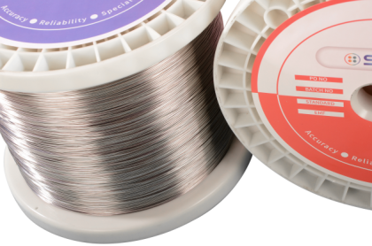
<65La ventaja del sensor de temperatura del termopar es que su estructura es relativamente simple. Es ampliamente utilizado por semiconductores o conductores de diferentes materiales. Los dos conductores forman un circuito cerrado, y se genera una fuerza electromotriz en el bucle. Observar la fuerza electromotriz térmica puede analizar la temperatura del objeto. Por lo tanto, para garantizar la precisión de los resultados de la medición, la preparación de los sensores de temperatura del termopar requiere requisitos estrictos en los puntos calientes y los materiales, y necesita tener propiedades químicas y físicas con alta estabilidad. Su coeficiente de temperatura de resistencia debe ser pequeño, y su conductividad debe ser alta. Existe una relación lineal obvia entre la fuerza electromotriz y la fuerza electromotriz y la temperatura térmica, lo que garantiza la reproducibilidad.
<66
<67
3.5. Termalresistancesensor
<68
<69Los sensores de termopar miden la temperatura a través de la fuerza electromotriz térmica y limitan el rango de medición de temperatura. Para los objetos de -200 ° C a 500 ° C, se pueden aplicar grados de resistencia térmica Celsius. Su principio de trabajo es medir la temperatura a través de la relación lineal entre el valor de resistencia de un semiconductor o conductor y el cambio de temperatura. En general, el valor de resistencia de los materiales metálicos comunes aumentará en un 0.4%~ 0.6%cuando cada vez la temperatura aumente en 1 ° C. Esta relación lineal puede completar la medición de la temperatura ambiente. El sensor de resistencia térmica detecta el cambio de la temperatura circundante por el cambio específico del valor de resistencia del termistor, y la temperatura real del objeto medido se puede calcular de acuerdo con el valor de resistencia medido. El sensor de resistencia térmica puede detectar la temperatura más baja y el rango de temperatura más alto generalmente es de -200 ° C ~ 500 ° C.
<70
<71
Las piezas utilizadas en el sensor son principalmente metal, y los siguientes principios deben cumplirse en términos de selección de material:
<72
<73(1) el valor de resistencia del material resistivo y la temperatura del objeto deben mantener una relación lineal armoniosa y mantener la estabilidad a largo plazo;
<74
<75
(2) el material resistivo cuanto mayor sea la resistividad, menor es la capacidad de calor de sus accesorios de metal y más rápido es la respuesta de detección de temperatura;
<76
<77
(3) El material es rentable y el precio también es muy razonable;
<78
<79
(4) Seleccione el material de acuerdo con el rango de temperatura a medir para garantizar propiedades físicas más estables.
<80
<81
4. Métodos de prueba
<82
<83El método de detección de rendimiento del sensor de temperatura debe analizarse en función de los escenarios de aplicación reales del sensor. Por ejemplo, el sensor que detecta la temperatura del refrigerante del motor no puede probarse con una llama abierta durante la prueba de rendimiento; de lo contrario, el sensor se dañará gravemente. No importa qué parte se eliminará cuando se detecte el sensor, la potencia debe cortarse primero, de lo contrario, la eliminación de la parte puede causar corriente excesiva o aumento de voltaje dentro del sensor, dañando así el sensor.
<84
<85
El sensor de temperatura preparado por la resistencia del platino necesita probar el tiempo de respuesta térmica de la resistencia de platino primero. Gire la resistencia de platino con la temperatura inicial en un baño de temperatura constante, calcule el tiempo para que la temperatura inicial alcance el 63.2% de la diferencia entre la diferencia entre la temperatura media y la constante de tiempo registrada. Establezca un tiempo de muestreo de 10s, pruebe cada segundo y registre la constante de tiempo.
<86
<87Se requiere una prueba característica R-T al probar el rendimiento térmico del termistor de coeficiente de temperatura negativa NTC. Debido a un cierto rango de temperatura, el valor de resistencia del termistor NTC mostrará una tendencia descendente no lineal a medida que aumente la temperatura, es decir, en el proceso de aumento de la temperatura, su valor de resistencia mostrará una tendencia de cambio gradual. Esto no puede medir la temperatura con precisión. Para este tipo de relación no lineal entre la temperatura y la resistencia, es necesario estudiar sus parámetros a través de una gran cantidad de experimentos, y obtener la relación de mapeo entre la temperatura y la resistencia al ajustar la relación curva por método de regresión.
<88
<89La precisión de la curva R-T del termistor NTC está directamente relacionada con el rendimiento, por lo que la medición de resistencia es un vínculo extremadamente importante. Métodos más típicos, como el método del puente DC y el método de corriente constante. El método del puente DC es usar 4 resistencias, entre las cuales las resistencias medidas forman un puente, determinar el ajuste de resistencia para equilibrar el puente y recolectar y distribuir las resistencias medidas a través del principio de la división de voltaje eléctrico. El método de corriente constante es un método de experimento de control. Conecte dos resistencias en serie en un circuito cerrado, use un voltímetro para obtener datos de voltaje en tiempo real en ambos extremos y ajuste las resistencias en el experimento de comparación para que los valores del voltímetro sean los mismos y se mide la resistencia medida.
<90
<91
4.1. Detección del sensor de temperatura del agua
<92
<93El sensor de temperatura necesita desenchufar el conector de cables en el proceso de detección de temperatura del agua. Si la temperatura del agua es diferente, necesita usar el medidor de resistencia para detectar. Durante la prueba, es necesario asegurarse de que el valor de resistencia cumpla con los datos que se muestran en la Tabla1 a continuación. Durante la instalación del sensor, es necesario conectar los cables a tiempo para asegurarse de que el interruptor de encendido esté en el estado ON, el valor de voltaje en ambos extremos de THW y E2 debe ser 0.1 ~ 1.0V y la temperatura del agua está en 80 ° C. Si no se muestra ningún voltaje cuando se mide, se requiere una inspección sistemática adicional.
<94
<95
<96
<97
<98
<99
temperatura del agua/â ° C
<100
<101
<102
<103
Resistencia/Kî ©
<104
<105
<106
<107
<108
<109
0
<110
<111
<112
<113
4 ~ 7
<114
<115
<116
<117
<118
<119
20
<120
<121
<122
<123
2 ~ 3
<124
<125
<126
<127
<128
<129
40
0.9 ~ 1.3
<138
60
<140
<143
0.4 ~ 0.7
<145
<147

<149
80
<150
<151
<152
<153
0.2 ~ 0.4
<154
<155
<156
<157
<158
<159
<160
Tabla 1
<161
<162
4.2. Detección del sensor de temperatura del aire de admisión
<163
<164
El método de detección del sensor de temperatura del aire de admisión es el mismo que el del sensor de temperatura del agua, y es necesario cortar la potencia del sensor en el tiempo durante la inspección. Luego, asegúrese de que el interruptor de encendido esté en el estado ON y analice si hay voltaje en las terminales de THW y E2. El rango de voltaje es de 0.5 ~ 3.4 V, y la temperatura del agua debe ser de 20 ° C. Si no se muestra ningún voltaje cuando se mide, también se requiere una inspección adicional para averiguar la causa de la falla.
<165
<166
4.3. Detección del sensor de temperatura del refrigerante y sensor de temperatura del aire de admisión
<167
<168Al probar, el sensor debe instalarse en el motor, y se prepara un voltímetro para conectarse al terminal del sensor. Según las diferentes temperaturas del refrigerante, el voltímetro se mostrará. Ocasionalmente, aparecerá el valor de resistencia interna, lo cual solo es posible cuando la ECU está conectada al sensor de temperatura del refrigerante del motor y la temperatura alcanza 49 ° C. El cambio del valor de resistencia afectará la matriz de presión entre los dos polos y también cambiará.
<169
Durante el uso del sensor, su sistema informático puede experimentar algunas fluctuaciones, que son normales y solo deben controlarse dentro del rango permitido. Al mismo tiempo, si el sensor de temperatura del aire de admisión se instala en la posición del motor, se debe conectar un voltímetro entre los dos terminales para mostrar el valor de temperatura. El estándar numérico a menudo se muestra en la Tabla 2. En el proceso de diseño e inspección del rendimiento del sensor de temperatura, es necesario realizar un análisis detallado en el acuerdo estricto con los estándares existentes, y al mismo tiempo hacer ajustes en combinación con diferentes escenarios de uso y uso Requisitos para garantizar que el sensor de temperatura pueda satisfacer realmente las necesidades de detección reales.
temperatura/° F
<178
<79
<80
<181
Voltaje/V
<82
<183
<184
<85
temperatura/° F
<86
<87
<188
<189
Voltaje/V
<190
<191
<192
<193
<194
<195
-20
<196
<198
<9 199
4.81
<2 200
<201
<202
<203
140
<204
<205
<206
<207
1.52
<208
<209
<210
<211
<212
<213
0
<214
<215
<216
<217
4.7
<218
<219
<220
<221
160
<222
<223
<224
<225
1.15
<226
<227
<228
<229
<230
<331
20
<332
<333
<334
<335
4.47
<336
<337
<338
<339
180
<240
<241
<242
<243
0.86
<244
<245
<246
<247
<248
<249
40
<250
<251
<252
<253
4.11
<254
<255
<256
<257
200
<258
<259
<260
<261
0.65
<262
<263
<264
<265
<266
<267
60
<268
<269
3.67
220
| |
| 0.48
<280
<281
<282
<283
<284
<285
80
<286
<287
<288
<289
3.08
<290
<291
<292
<293
240
<294
<295
<296
<297
0.35
<298
<299
<300
<301
<302
<303
100
<304
<305
<306
<307
2.51
<308
<309
<310
|
260
|
0.28
|
| |
| |
| |
| |
Tabla 2


 Network IPv6 compatible con